555 Timer Internal Schematic - Learning The 555 From The Inside Hackaday / These pins are used to connect an internal oscillator to the microcontroller.
byAdmin-
0
555 Timer Internal Schematic - Learning The 555 From The Inside Hackaday / These pins are used to connect an internal oscillator to the microcontroller.. Apr 07, 2021 · the following schematic depicts the internal circuit of the ic 555 operating in astable mode. As the name specifies, a monostable multivibrator has only one stable state. Derivatives provide two (556) or four (558) timing circuits in one package. Pin 20 is a ground pin. When a high condition is applied to the en pin, the reset condition is relieved and the 555 timer will begin to oscillate.
Pin 20 is a ground pin. We can use the 555 as a timer for up to 10 minutes. This is the basic mode of operation of the ic 555. In 2017, it was said over a billion 555 timers are pr. 555 timer helpers schematic the addition of a capacitor to the trigger will not work for short output pulses as there is also a short delay in the recovery of the trigger terminal voltage.
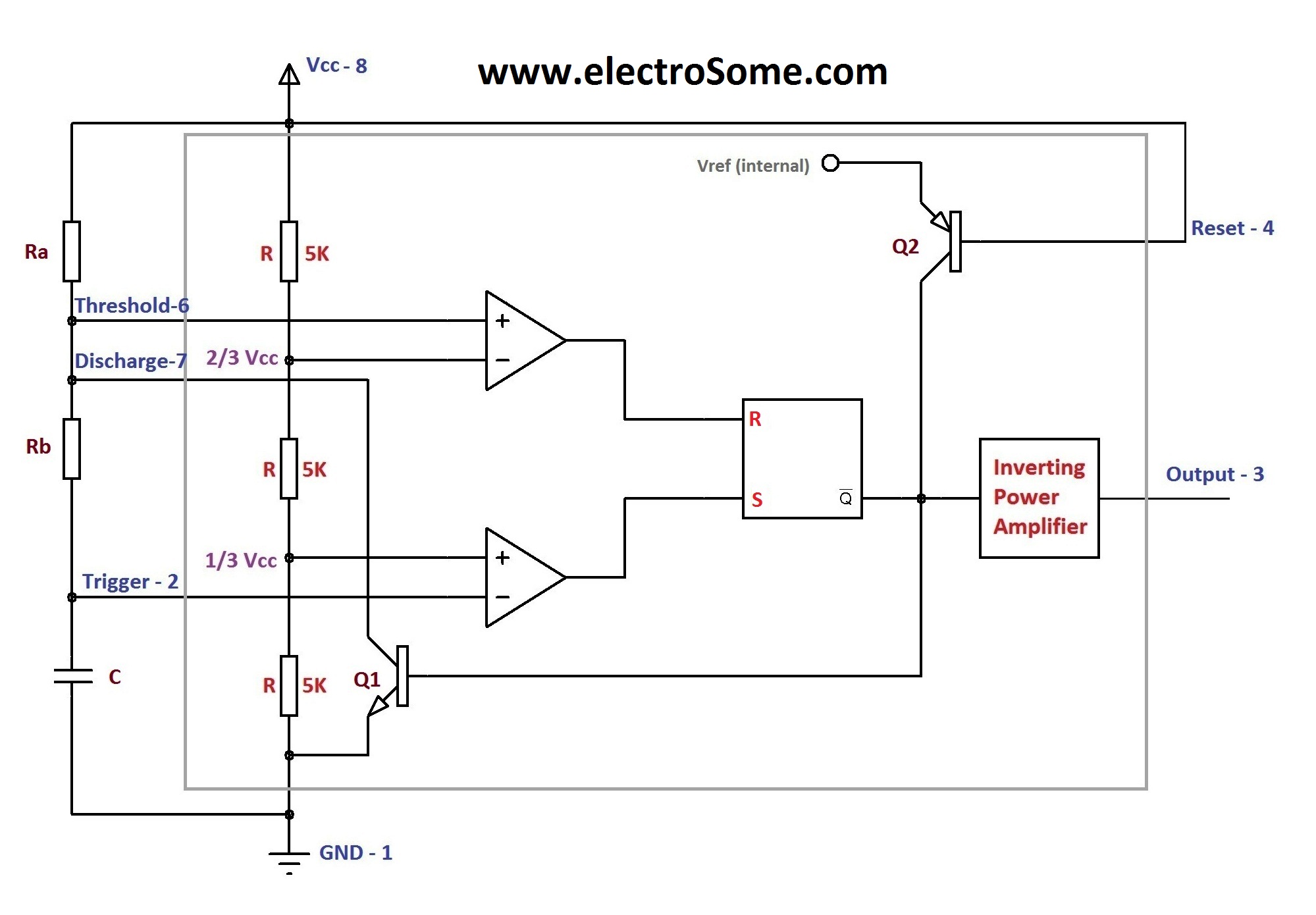
Astable Multivibrator Using 555 Timer from electrosome.com When a high condition is applied to the en pin, the reset condition is relieved and the 555 timer will begin to oscillate. This circuit is also called a delay. Simple ne555 ic tester circuit diagram. If you would like to use any of these ideas, do some testing before using the lm555 or lm556 timer in an actual circuit. Apr 07, 2021 · the following schematic depicts the internal circuit of the ic 555 operating in astable mode. It was commercialized in 1972 by signetics. Jun 16, 2015 · the following figure is the schematic of ic 555 as a monostable multivibrator. This is the basic mode of operation of the ic 555.
But, this is only possible when we don't use any external memory.
Apr 07, 2021 · the following schematic depicts the internal circuit of the ic 555 operating in astable mode. A resistor and a capacitor. Jun 16, 2015 · the following figure is the schematic of ic 555 as a monostable multivibrator. But, this is only possible when we don't use any external memory. It was commercialized in 1972 by signetics. As the name specifies, a monostable multivibrator has only one stable state. In 2017, it was said over a billion 555 timers are pr. This is the basic mode of operation of the ic 555. If you would like to use any of these ideas, do some testing before using the lm555 or lm556 timer in an actual circuit. This circuit is also called a delay. 555 timer helpers schematic the addition of a capacitor to the trigger will not work for short output pulses as there is also a short delay in the recovery of the trigger terminal voltage. We can use the 555 as a timer for up to 10 minutes. Port2 includes pin21 to pin28 which can be configured as input output pins.
The second 555 timer helper will extend the timers output duration without having to use large values of r1 and/or c1. Port2 (pin 21 to pin28): When a high condition is applied to the en pin, the reset condition is relieved and the 555 timer will begin to oscillate. Derivatives provide two (556) or four (558) timing circuits in one package. A resistor and a capacitor.
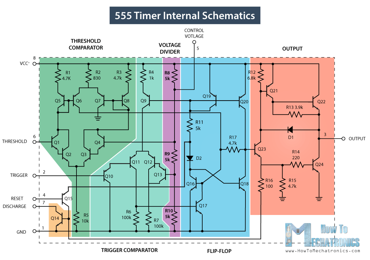
555 Timer Ic Working Principle Block Diagram Circuit Schematics from howtomechatronics.com If you would like to use any of these ideas, do some testing before using the lm555 or lm556 timer in an actual circuit. 555 timer helpers schematic the addition of a capacitor to the trigger will not work for short output pulses as there is also a short delay in the recovery of the trigger terminal voltage. Jun 16, 2015 · the following figure is the schematic of ic 555 as a monostable multivibrator. An open collector is a common type of output found on many integrated circuits (ic), which behaves like a switch that is either connected to ground or disconnected.instead of outputting a signal of a specific voltage or current, the output signal is applied to the base of an internal npn transistor whose collector is externalized (open) on a pin of the ic. Apr 15, 2020 · people know it as the 555 timer ic. This is the basic mode of operation of the ic 555. But, this is only possible when we don't use any external memory. These pins are used to connect an internal oscillator to the microcontroller.
In 2017, it was said over a billion 555 timers are pr.
If you would like to use any of these ideas, do some testing before using the lm555 or lm556 timer in an actual circuit. It requires only two extra components to make it work as a monostable multivibrator: These pins are used to connect an internal oscillator to the microcontroller. The second 555 timer helper will extend the timers output duration without having to use large values of r1 and/or c1. 555 timer helpers schematic the addition of a capacitor to the trigger will not work for short output pulses as there is also a short delay in the recovery of the trigger terminal voltage. Pin 20 is a ground pin. But, this is only possible when we don't use any external memory. Learn by doing is the best. Port2 includes pin21 to pin28 which can be configured as input output pins. Jun 16, 2015 · the following figure is the schematic of ic 555 as a monostable multivibrator. Derivatives provide two (556) or four (558) timing circuits in one package. This is the basic mode of operation of the ic 555. Simple ne555 ic tester circuit diagram.
Port2 (pin 21 to pin28): The 555 timer ic is an integrated circuit (chip) used in a variety of timer, delay, pulse generation, and oscillator applications. We can use the 555 as a timer for up to 10 minutes. Jun 16, 2015 · the following figure is the schematic of ic 555 as a monostable multivibrator. As the name specifies, a monostable multivibrator has only one stable state.
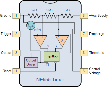
555 Timer Wiki Wiki Jmehan Com from wiki.jmehan.com Port2 includes pin21 to pin28 which can be configured as input output pins. If you would like to use any of these ideas, do some testing before using the lm555 or lm556 timer in an actual circuit. When a high condition is applied to the en pin, the reset condition is relieved and the 555 timer will begin to oscillate. Jun 16, 2015 · the following figure is the schematic of ic 555 as a monostable multivibrator. Port2 (pin 21 to pin28): Simple ne555 ic tester circuit diagram. 555 timer helpers schematic the addition of a capacitor to the trigger will not work for short output pulses as there is also a short delay in the recovery of the trigger terminal voltage. This circuit is also called a delay.
A resistor and a capacitor.
In 2017, it was said over a billion 555 timers are pr. These pins are used to connect an internal oscillator to the microcontroller. Derivatives provide two (556) or four (558) timing circuits in one package. We can use the 555 as a timer for up to 10 minutes. Pin 20 is a ground pin. There will be minor internal circuitry differences between 555 timer ic's from the various manufacturers but they all should be useable for the circuits on this page. This is the basic mode of operation of the ic 555. The second 555 timer helper will extend the timers output duration without having to use large values of r1 and/or c1. When a high condition is applied to the en pin, the reset condition is relieved and the 555 timer will begin to oscillate. Port2 includes pin21 to pin28 which can be configured as input output pins. An open collector is a common type of output found on many integrated circuits (ic), which behaves like a switch that is either connected to ground or disconnected.instead of outputting a signal of a specific voltage or current, the output signal is applied to the base of an internal npn transistor whose collector is externalized (open) on a pin of the ic. Jun 16, 2015 · the following figure is the schematic of ic 555 as a monostable multivibrator. Learn by doing is the best.
As the name specifies, a monostable multivibrator has only one stable state 555 timer schematic. Simple ne555 ic tester circuit diagram.